In the design of artificial satellites and space vehicles, the function of the thermal control system (TCS) is to keep all parts of the satellite within acceptable temperature ranges during all phases of the mission and to dissipate the heat produced by the satellite into space. This can be achieved through a combination of passive and active design techniques.
Spacecraft thermal control is required for two main reasons: Electronic and mechanical equipment usually operate efficiently and reliably only within relatively narrow temperature ranges, and most materials have non-zero coefficients of thermal expansion, and hence, temperature changes can result in thermal distortion.
During the life cycle of units used in satellites or spacecraft, their performance should be evaluated by simulating the operating environment under high-vacuum conditions with different thermal cycles. While the high vacuum is implemented using different pumping systems, high and low temperatures are generated with the help of heating resistances and thermal walls using nitrogen as a heat-transfer medium.
The need for an efficient TCS is dictated by the technological/functional limits and the reliability requirements of all the equipment used onboard a spacecraft and, in the case of human missions, by the need to provide the crew with an adequate living/working environment. Almost all sophisticated equipment has specific temperature ranges in which it will function properly.
Recommended
The Importance of Power Systems for Space Missions
Thermal conductivity
Thermal conductivity is a material property and is independent of factors such as the size and shape of the material. The thermal resistance of any material depends on its area and thickness, which are essential factors when sizing a system to transfer heat from the package of a component to the heat sink, whether it is the frame or the container.
Space vehicles require the use of ultra-high-temperature ceramics. They are a family of ceramic materials with extremely high melting temperatures and a good thermal shock resistance, which find applications on satellites and space vehicles.
When calculating the heat transmission through the complete system, from the component package to the heat sink, the overall temperature difference is proportional to the sum of the individual thermal resistances, including the interface resistances along the contact surfaces between the materials.
The conductivity, therefore, depends on the physical-chemical characteristics of the material being analyzed. There is a correlation between the ability to transmit heat and the electricity of a material. As such, a thermal insulator is usually a terrible electrical conductor.
Passive design
Passive thermal control does not require input power for thermal regulation in a spacecraft or satellite. This can be achieved by using different methods that have been proven to be reliable and deliver low cost, volume, weight, and risk. The integration of multi-layer insulation (MLI), thermal coatings, and heat pipes are some examples of passive methods to reach thermal equilibrium in a spacecraft.
In a vacuum, heat is transferred by two means: radiation and conduction. The internal environment of a small, wholly enclosed satellite is usually dominated by the transfer of conductive heat, while the accumulation of energy and the external environment are guided exclusively by thermal radiation. The environment with thermal radiation is manipulated by using materials that have certain specific radiative properties, commonly referred to as solar absorbance (wavelengths in the range from about 0.3 μm to 3 μm) and IR emissivity (from about 3 μm to 50 μm).
Recently, flexible thermal belts have become a convenient way to control the temperature on small spacecraft, as the belt size is limited by reduced rigidity between the components. Flexible thermal belts can be applied to allow passive heat transfer to a heat sink and can be adapted to any specific design length.
Heat pipes are a closed-loop thermal-transfer technique that carries excess heat through temperature gradients, typically from electrical devices to a cooling surface. It is often a radiator itself or a heat sink thermally coupled to a radiator.
Active design
In addition to passive techniques, active cooling can offer numerous advantages. These include accurate temperature control, faster response, and the possibility of cooling the components below ambient temperature. An active thermal control system (ATCS) primarily consists of thermostatically controlled electric heaters, fluid circuits to transfer the heat dissipated by the equipment to the radiators, and Peltier thermoelectric coolers.
Peltier-effect thermoelectric devices can be used both as a cooling and a heating device. They are reversible through the Seebeck effect and can also be used as generators (for example, in solar panels).
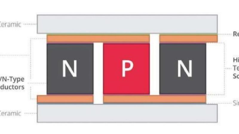
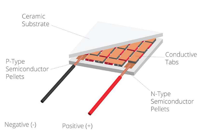
Therefore, like a solid-state heat pump (which does not require a fluid inside it for heat exchange), it is mainly formed by a series of junctions between two doped semiconductor materials of type N and type P, respectively — connected by a copper lamella.
An example of an innovative technology used for Peltier modules is CUI’s arcTEC structure, which counteracts the thermal stress effects of thermoelectric modules by incorporating a thermoconductive resin between the electrical interconnection and the ceramic of the module. The arcTEC structure replaces the traditional welding joint between the copper plating and the ceramic substrate (Fig. 1 and Fig. 2).
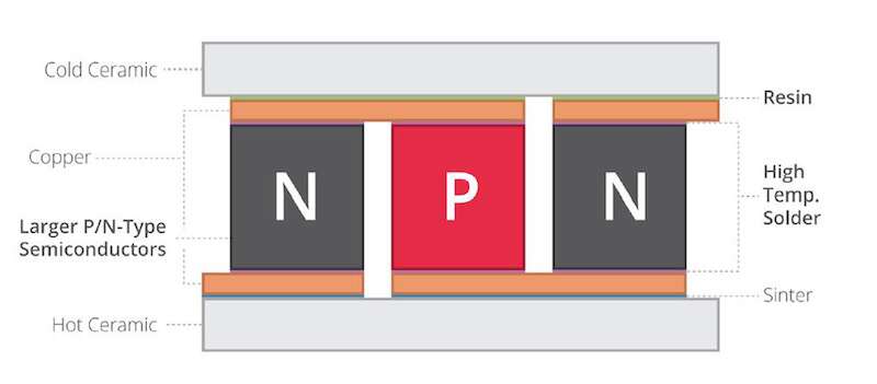
The combination of these substrates dramatically improves the reliability, performance, and cycle life of the Peltier modules made with the arcTEC structure, allowing them to replace the traditional thermoelectric coolers in the most demanding applications.
PID control for thermal management in spacecraft
A thermoelectric control system includes the Peltier element and the heat sink unit, temperature sensors to monitor hot and cold plates, and a control unit to ensure that the desired temperature is within a certain range.
Proportional-integral-derivative (PID) control (a control-loop feedback technique) is the universally accepted control algorithm in various industrial sectors. Robustness can be attributed to their simplicity and the full range of operating conditions, which allows designers to manage controls efficiently.
The PID control consists of three parameters (P, I, and D) expressed in an integral equation. A different system-transfer function can be obtained depending on its state conditions and a good choice of PID parameters.
Before the operation of the PID controller occurs, it must be adjusted to adapt to the dynamics of the process to be controlled. Designers provide the default values for the terms P, I, and D. However, the default values typically don’t provide the desired performance and sometimes lead to instability and control performance. Several methods are available to fine-tune the PID controllers, which require a lot of operator attention to select the best proportional gain, integral, and derivative values.
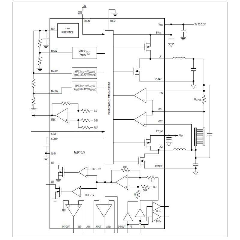
An example of a temperature controller for Peltier thermoelectric coolers (TECs) is Maxim Integrated’s MAX1978/MAX1979 devices. Designed for accurate temperature control of Peltier TEC modules, the device’s high integration offers a minimum of external components and fast time to market. The output current, rather than the voltage, is controlled directly to eliminate current peaks. A chopper-stabilized instrumentation amplifier and an integrator are provided to create a PID control. The instrumentation amplifier can interface with an external NTC or PTC thermistor, a thermocouple, or a semiconductor thermometer (Fig. 3).
Conclusion
Given the numerous variables to be considered and the diversity of thermal materials and assembly techniques available, thermal verification, based on the performance of the overall system, should be carried out in the initial phase of designing a new product. As with all aspects of engineering, significant changes in the project become increasingly expensive, long, and challenging to implement as the project progresses. For example, arranging the hottest components on the board in positions suitable for more effective heat dissipation can avoid a complicated thermal design or costly revision of the board and the risk of delaying the introduction of a new product.
Recommended
The Importance of Power Systems for Space Missions