Follow USB-IF’s test procedures for compliance
Article By : Mike Micheletti
The PD Compliance Plan requires that a power source meet all the underlying voltage and timing parameters during a power increase or decrease.
« Previously: Don't cut corners with USB PD compliance
Message, procedure, policy and timing tests
Many of the PD Compliance test assertions focus on PDOs (Power Delivery Objects) that define specific power and current levels that a device can source or sink. The editors of PD release 2.0 v1.2 specification revised the PD 1.0 Power Rules with the goal of making PD charger devices more interchangeable. All PD devices must now provide a single parameter called PDP (PD Power) that defines the maximum wattage that the device can either supply as a provider or sink as a consumer. By rule, a source should be able to charge any device with a lower PDP according to the parameters in Table 1.
![[USB-PD Tbl1 PowerRules PDOs]](/wp-content/uploads/sites/4/2020/04/USB-PD_Tbl1_PowerRules_PDOs.jpg)
*__Table 1:__ To be PD compliant, a Source reporting a PDP of “45W” must also report all the Fixed PDOs as shown in the log above. This allows the 45W PDP source to be downward compatible with devices designed for use with a lower PDP power supply.*
The Power Rules in Table 1 are verified in the TDA.2.1.4.1.1, where the tester captures the SOURCE CAPABILITY message and then verifies all the reported PDO’s are consistent with the voltages defined in Table 1. For example, A PD source that reports a PDP of “45W”, must advertise PDOs of 3A @ 5V, 3A @ 9V, 3A @ 15V; and 2.25A @ 20V. It may optionally report other PDOs as well. This PDP check is a new requirement added at the January 2016 USB Workshop. As with most new USB compliance requirements, there's a one-year waiver period for PD device implementations that may not yet support the newer requirements.
Sinks are also required to specify a PDP in their Sink Capabilities and this is verified in TDB.2.1.4.1.2. Here, the goal is to ensure a sink does not advertise a maximum current in their Sink Capabilities message over that PDP. In a related check, the test system intentionally advertises a source PDO that does not meet the sink’s minimum required current. The DUT, acting as a sink, is still required to make a valid REQUEST within the offered range but also set their Capability Mismatch bit within the REQUEST message.
TDA.2.2.2.1 is considered a critical test for safety and verifies that a source doesn't offer more than 3 A, on a 3 A-limited cable. The PD protocol mandates that devices should never offer power above 3 A unless the cable is rated for high-power operation. The recommended implementation for this test requires use a special "Unmarked Ra Cable" that presents the E-Marked cable termination (Ra), but doesn't embed the Electronic Marker in the cable. The special Ra-terminated cable is needed to "spoof" the DUT into initiating SOP (start of packet)-prime "Cable" DISCOVER messages. This lets the tester emulate the cable marker communication and directly respond when the DUT attempts to query the cable. The tester sends a DISCOVER CAPABILITIES response messages to indicate it's limited to 3 A. The DUT is supposed to see the 3 A limit and subsequently limit his advertised SOURCE CAPABILITIES to no more than 3 A. DUTs advertising 5 A power during this test would obviously fail compliance and potentially cause electrical or thermal damage to other USB devices. As you can see, Type-C cables capable of carrying high current aren't passive devices.
The PD Compliance Plan requires that a power source meet all the underlying voltage and timing parameters during a power increase or decrease (as defined in Chapter 7 of the PD base specification). For DRP devices, this is verified in TDA.2.3.2.2 where the tester assumes the sink role and programmatically steps through all available source PDOs. The test starts with a power role swap to make the DUT into the power source, then the tester issues a series requests starting from PDO #1 until every possible transition between all available PDOs is complete.
With each new power contract, the tSrcTransition timer is verified and this requires the source to wait at least 25 ms, but not more than 35 ms, before it starts increasing the voltage. This is just one the many timing widows the PD standard defines that serve as guard-bands during transient load conditions to ensure the sink has sufficient time to prepare during power changes, resets and role swaps. Figure 2 shows a simplified negotiation diagram (click to enlarge).
![[USB-PD Fig2 flowchart]](/wp-content/uploads/sites/4/2020/04/USB-PD_Fig2_flowchart.jpg)
*__Figure 2:__ Successful PD contract negotiation requires five steps: the source advertises its capabilities in a Source Capabilities message, the sink makes a power Request, the source sends Accept followed by PS-Ready after the new voltage level is reached, the sink begins using the new power level.*
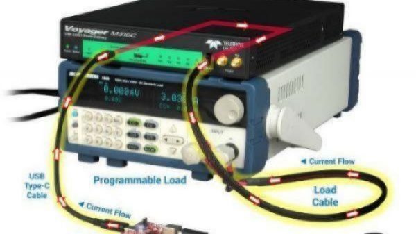
A deeper dive into the TDA.2.3.2.2 reveals 18 specific assertions that must be checked for each power transition. These are actually defined in TDB.2.2.7.1, which is considered a secondary test that is verified anytime a positive or negative power transition is observed during a primary test. Here again the test system is used to mimic real-world PD device behaviours by drawing up to 5 A current over VBUS like a real PD Sink. To perform these checks properly requires a programmable load generator as part of the test setup (Figure 3). As the tester requests each voltage transition, the load box pulls the appropriate current to verify the power supply end-to-end. The external load box can be fully automated using USB-TMC class commands to exchange measurement data with the PD Compliance application.
![[USB-PD Fig3 test setup 600x445]](/wp-content/uploads/sites/4/2020/04/USB-PD_Fig3_test_setup_600x445.jpg)
*__Figure 3:__ Typical test setup for the PDO transition test utilises a PD emulator and programmable load to verify the timing, electrical and protocol compliance for DUTs acting as a power source.*