Test serial-data clock jitter via LCC
Article By : Gary Giust, Jayaprakash Balachandran, Bidyut Sen
When testing, use an oscilloscope with sufficient deep memory to capture the lowest-frequency expected to cause problems in the system.
« Previously: Define serial-data jitter spec with clock analysis
Validation involves connecting several oscillators as reference clocks to a Cisco Systems 25.78125Gbps SERDES and performing 100GBASE-CR4 transmitter compliance testing. The first step is to separately characterise four different (competing) commercial 156.25MHz LVPECL 5mm x 7mm clock oscillators using the previous methodology. The reference clock applied to the SERDES clock input is 156.25MHz. Inside the SERDES, the transmit PLL multiplies this clock frequency by a factor of 165 to create a bit-rate clock at 25.78125GHz. The bit-rate clock times the serial-data onto the channel.
![[Jitterlabs figure7 cr]](/wp-content/uploads/sites/4/2020/04/Jitterlabs_figure7_cr.jpg)
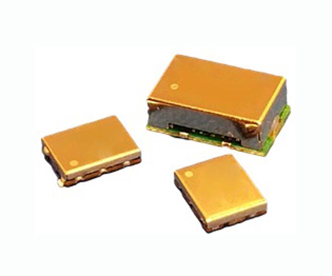
Figure 1: The "clock" devices under test are discrete oscillators in a leadless chip carrier (LCC) package (usually 6 pins, 5mm x 7mm footprint).
The clock oscillators frequencies must be much than the bit-clock's frequency to avoid injecting EMI (and other issues) that can occur because of routing their clock signal across a PCB. Every SERDES (Ethernet, fibre channel, Infiniband, USB, SONET, etc.) typically requires a low-jitter reference clock. Each oscillator is mounted on its own dedicated evaluation board for characterisation. Since high-speed serial-data standards typically define the RX, but not the TX, jitter filter, we also characterise the SERDES TX PLL jitter transfer characteristic and use it to create a model for the TX jitter filter.
Completing the methodology outlined above provides dual-Dirac values of DJREFCLK and RJREFCLK (at 1E-5 BER) for each oscillator. The 100GBASE-CR4 standard limits serial-data jitter at a BER of 1E-5 at the physical-layer. The standard relies on FEC (in a software layer) to reduce this BER down to a much lower level. We try to follow the standard as much as possible when analysing jitter. Thus, if serial-data jitter gets evaluated at 1E-5 BER, then we do the same for analysing reference clock jitter. In practice, the methodology presented here is flexible enough to accommodate any BER of interest.
We then solder one oscillator onto a SERDES evaluation board to use as a reference clock. Transmitter compliance testing is performed using Keysight 100GBASE-CR4 compliance software running on an equivalent-time oscilloscope (DSA-X 86100D) with precision waveform analyser (86108B).
![[Jitterlabs figure8 cr]](/wp-content/uploads/sites/4/2020/04/Jitterlabs_figure8_cr.jpg)
Figure 2: Test setup for performing 100GBASE-CR4 transmitter compliance measurements using Keysight DSA-X 86100D equivalent-time oscilloscope.
The compliance software outputs two numbers of interest: effective uncorrelated TJ at a BER of 1E-5 (TJTX) and effective bounded uncorrelated jitter (BUJTX). After running the compliance test several times to accumulate statistics for these numbers, we change the oscillator and repeat the compliance test. We perform this procedure separately for each of the four oscillators, resulting in a set of measured TJTX and BUJTX values for all four oscillator setups, each using the same SERDES.
After collecting the compliance data, we evaluate it by extracting, for each oscillator setup, the SERDES-specific jitter, then add this jitter to the other oscillators' jitter to predict their TJTX compliance results. Let's step through the math to predict TJTX for one oscillator setup. Note that in the discussion below, all jitter variables have peak-to-peak units, and TJ and RJ are assumed to be measured at a BER of 1E-5.
Jitter equation
Deterministic jitter is composed of DDJ, DCDJ and BUJ. Because 100GBASE-CR4 testing measures transmitter jitter on a specific transition in a PRBS9 pattern (eliminating DDJ) and rising-only clock edges are used to clock data out of the transmitter (eliminating DCDJ), only the BUJ component is present in DJ. Thus the dual-Dirac model for TJ at the transmitter output is simply,
![[Jitterlabs equation1]](/wp-content/uploads/sites/4/2020/04/Jitterlabs_equation1.jpg)
for the first two oscillator setups, where _1 and _2 indicate the first and second setup, respectively. Since DJ adds linearly and RJ as RSS, we also know,
![[Jitterlabs equation2 cr]](/wp-content/uploads/sites/4/2020/04/Jitterlabs_equation2_cr.jpg)
where BUJREFCLK equals an oscillator's dual-Dirac DJ (obtained using the above methodology), since reference-clock jitter is uncorrelated to the data pattern.
We compute the SERDES jitter using equations 3 and 5 as
![[Jitterlabs equation3 cr]](/wp-content/uploads/sites/4/2020/04/Jitterlabs_equation3_cr.jpg)
where we know BUJTX_1 and RJTX_1 from the measured compliance data, and BUJREFCLK_1 and RJREFCLK_1 from the measured methodology data.
Substituting equations 4 and 6 into equation 2 produces,
![[Jitterlabs equation4 cr]](/wp-content/uploads/sites/4/2020/04/Jitterlabs_equation4_cr.jpg)
which lets us predict the compliance data for TJTX_2 using the computed SERDES jitter and the measured methodology data for the second oscillator. To summarise, we're using the first oscillator's methodology data to compute the SERDES-specific jitter, which we then add to the second oscillator's methodology data to predict TJTX_2.
Because the only item changing during compliance testing is the oscillator, we can also solve for the SERDES-specific jitter using the third, and separately, forth oscillator, each time using the SERDES-specific values to predict TJTX_2. Doing so results in three predictions for TJTX_2. We use this data to compute an average prediction for TJTX_2, and a 95% confidence interval for this average prediction.
We repeat this procedure to separately compute average predictions and confidence intervals for TJ_TX1, TJ_TX3, and TJ_TX4. Figure 3 summarises the results.
![[Jitterlabs figure9 cr]](/wp-content/uploads/sites/4/2020/04/Jitterlabs_figure9_cr.jpg)
Figure 3: Measured versus predicted 100GBASE-CR4 transmitter compliance shows a tighter prediction range using this method. The agreement between measured and predicted TJTX is excellent, with a maximum error of 2.5mUIPP (e.g. 100 fsPP) among the four oscillators.
When testing, it's important to use an oscilloscope with sufficiently deep memory to capture the lowest-frequency content that can be expected to cause problems in the system of interest. For example, if a system observes TIE jitter down to 1kHz, then capturing a reference-clock waveform at 40Gsamples/s using a real-time oscilloscope requires a memory depth of (40Gsamples/s/1kHz),or 40Mpoints. The oscilloscope also needs to be configured properly for measuring jitter, particularly its vertical resolution. To eliminate environmental noise, place any exposed circuit boards in a shielded enclosure and use a power supply whose noise signature is representative of that observed in the intended system and environment. It's also important to apply a jitter filter that accurately models the real system. Industry standards typically define the jitter filter for the receiver, but not for the transmitter. We need to obtain an accurate model of the transmit-PLL jitter transfer function by contacting the SERDES manufacturer, or measuring it yourself in the lab. The transmit-PLL jitter filter model should include the correct bandwidth (e.g. use the highest bandwidth for worse case), roll-off (e.g. first or second order and peaking (if any).
To a certain extent, clock devices are general purpose in nature, which is reflected in their datasheet jitter specifications. The methodology described reports clock jitter in the natural language of high-speed serial-data standards, which greatly simplifies the evaluation and selection of reference clocks to use with those standards.
This article first appeared on EDN.
« Previously: Define serial-data jitter spec with clock analysis